
Heller Ligier JS11 1/12 - update 01 May


-
Chinamalc
Topic author - Best of the Rest

- Posts: 514
- Joined: Fri Oct 14, 2005 11:06 am
- Location: about 1985
- Status: Offline
Re: Heller Ligier JS11 1/12
Sandrino!!!!
1,000,000 thanks!
Now - anyone got a copy of F1 Modeling No 19 I could buy?
Malc.
1,000,000 thanks!
Now - anyone got a copy of F1 Modeling No 19 I could buy?
Malc.


Re: Heller Ligier JS11 1/12
Let me guess! Which model it talks about?Chinamalc wrote: Now - anyone got a copy of F1 Modeling No 19 I could buy?
Malc.
PS: beware: some of the ics are 1980's JS11/15!!
Tip: if it has full engine cover and brakes inside rear wheels, it's 1980!!!
Re: Heller Ligier JS11 1/12
Here we gooo!!!  Note there's a close up of FW07's gearbox tail light, and some pics of the Copersucar F6 for Jens aka JM


Re: Heller Ligier JS11 1/12
Still have N°19 in my stash, just pm me and we find a solutionChinamalc wrote:Sandrino!!!!
1,000,000 thanks!
Now - anyone got a copy of F1 Modeling No 19 I could buy?
Malc.
Take a stand!
-
Chinamalc
Topic author - Best of the Rest
- Posts: 514
- Joined: Fri Oct 14, 2005 11:06 am
- Location: about 1985
- Status: Offline
Re: Heller Ligier JS11 1/12
Hi James,
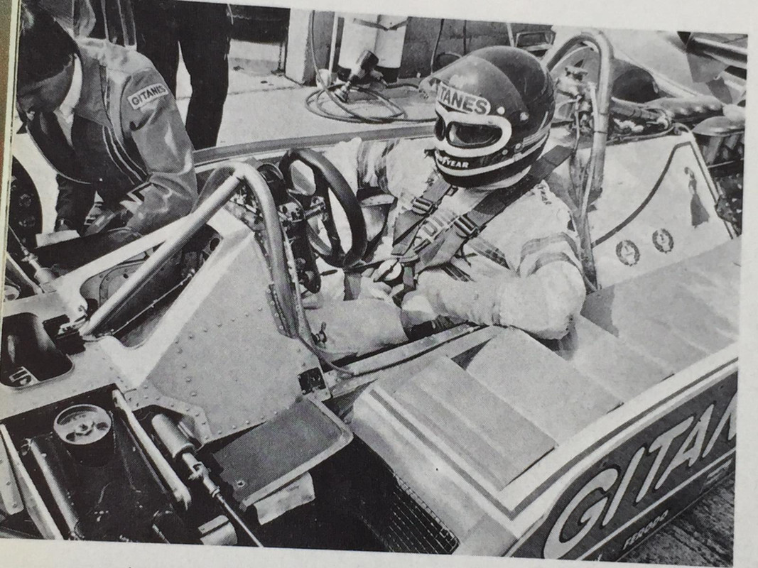
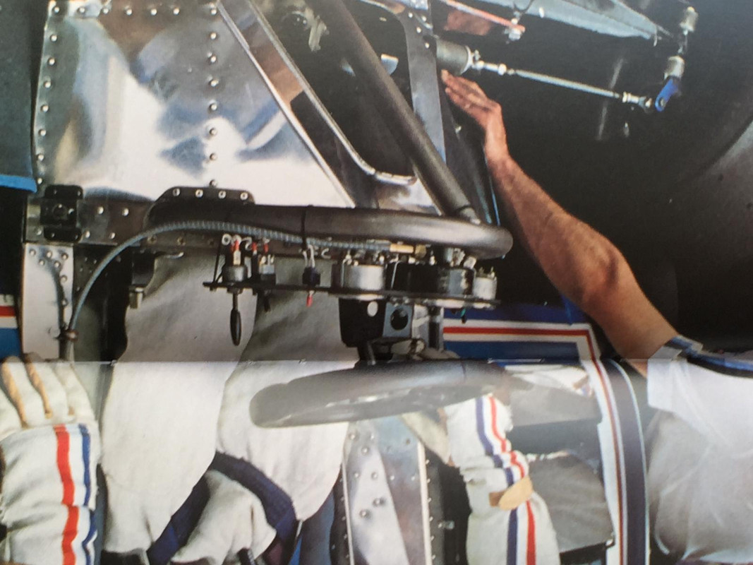
Thanks - fantastic!, photo 19 of the inside of the sidepod is very interesting and answers some questions!
GP-Models - PM sent.
Malc.
Thanks - fantastic!, photo 19 of the inside of the sidepod is very interesting and answers some questions!
GP-Models - PM sent.
Malc.
-
Chinamalc
Topic author - Best of the Rest
- Posts: 514
- Joined: Fri Oct 14, 2005 11:06 am
- Location: about 1985
- Status: Offline
Re: Heller Ligier JS11 1/12
So again, huge thanks to JamesB, Sandrino and Guido for providing great reference material, and proving once again what a great site this is!
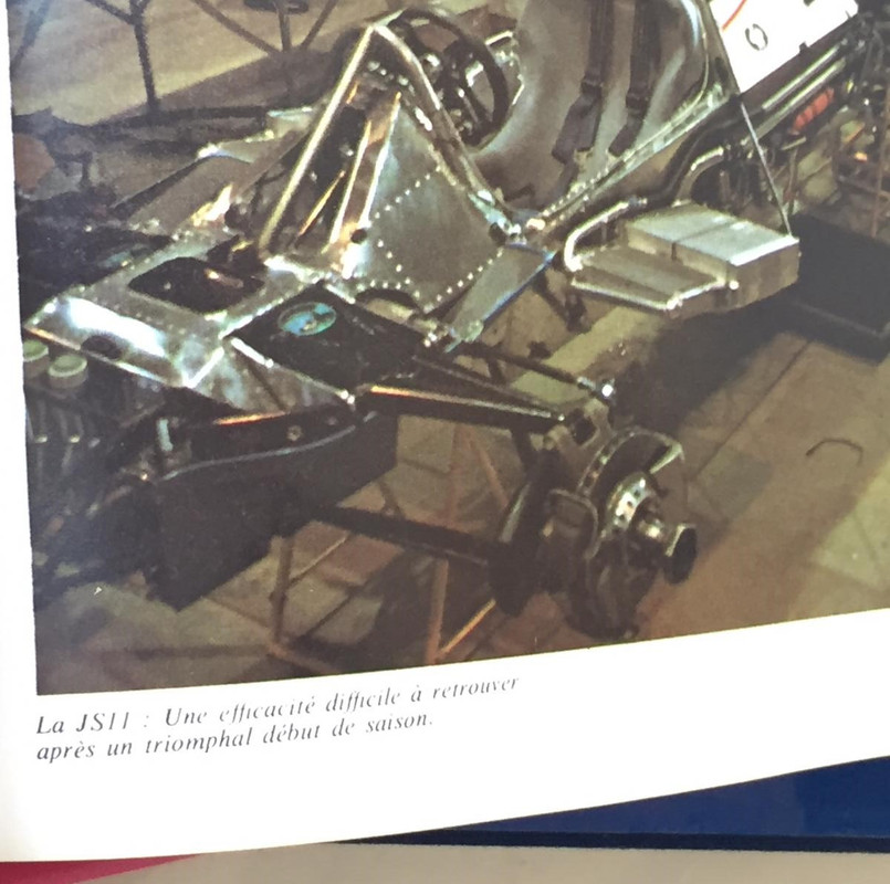
More engine stuff and suspension.
The rather anaemic spark box was removed from the fuel injection pump and made wider and deeper (I compared it to the Tamiya part)
I cut out a section from the oil tank to make room for the air start motor
Filled with half a piece of tube split down the centre
Air start motor was spun in a drill chuck and the grooves added and end rounded with file and sandpaper.
Final check with the damper in place to make sure it all clears, new spring seats were added further up the damper body.
The intake trumpets look like they could not suck enough air for an asthmatic lawn mower let alone 450HP of Ford DFV, so were opened up with a drill and sand paper glued to a tapered dowel which also removed the internal join line.
More engine stuff and suspension.
The rather anaemic spark box was removed from the fuel injection pump and made wider and deeper (I compared it to the Tamiya part)
-
Chinamalc
Topic author - Best of the Rest
- Posts: 514
- Joined: Fri Oct 14, 2005 11:06 am
- Location: about 1985
- Status: Offline
Re: Heller Ligier JS11 1/12
Cont'd
The rear brakes are very square in shape, so some finessing was required - before
After
I drilled the periphery of all the brake discs (20 x 1mm holes in each one!) At some races the discs had slots, but I found that Ligier also used discs with plain holes as below.
And assembled with disc and rather thin pads! I now think the whole calliper is too narrow, with the extra being required on the inboard side, but to change this would mean the brake disk would have to be moved outboard with subsequent changes to the drive shafts, I will have to think about this……
The inboard side of the front brakes were filled to make room for the brake pipe fitting which will be located in the centre of the modified face.
Outboard face on the left, modified inboard face on the right.
Next I modified the front and rear upper wishbones, as kit they are just flat plates with square edges.
I removed the moulded in damper tops from the inboard ends, (sorry no before photos!) added 30thou card to the top of each wishbone profiled to a slight curve, the edges of the wishbones were also rounded then the stiffener from 5thou card added across the pivot point.
After removing the moulded in damper tops and modified the ends, short lengths of tube were superglued back on to replace the removed pieces, afterwards the middle piece of tube was sawn out ensuring the ends are perfectly inline.
JamesB - hope you like this!
The rear brakes are very square in shape, so some finessing was required - before
Outboard face on the left, modified inboard face on the right.
I removed the moulded in damper tops from the inboard ends, (sorry no before photos!) added 30thou card to the top of each wishbone profiled to a slight curve, the edges of the wishbones were also rounded then the stiffener from 5thou card added across the pivot point.
-
Chinamalc
Topic author - Best of the Rest
- Posts: 514
- Joined: Fri Oct 14, 2005 11:06 am
- Location: about 1985
- Status: Offline
Re: Heller Ligier JS11 1/12
Cont'd
New springs wound from copper wire, the instructions call for the springs to be 10mm long which for the rears is about half as long as they need to be! (And I have moved the lower damper mount up a few mm). New shock tops made from tube and square rod
The front wishbones were slit half way through with the razor saw of doom across the pivot point, allowing a slight bend to be put in, closing up the saw cut which was then glued, this allows the repositioning of the pivot point to the centre of the wishbone sides (as scale) rather than underneath (as moulded) without changing the geometry.
Small fillets of Milliput were added to radius the inside corners of the damper tops and the inboard wishbone pivot points to finish them off.
Original shock tops for reference
Note the bend in the top wishbone and new centre pivots
I originally thought the centre of the front wishbones was recessed like the Lotus 49 so were made like this, but they are not, so I filled them back in.
The front uprights had the top vertical pivot pin removed and replaced with a horizontal pivot from 1mm wire. I raided my Wife’s craft box and found two glass beads that exactly fit inside the tube I had glued to the outboard end of the wishbone, the bead forms the spherical bearing the upright pivots around, the real car worked on same principal - but with better material science….
Thats all for now.
Malc.
New springs wound from copper wire, the instructions call for the springs to be 10mm long which for the rears is about half as long as they need to be! (And I have moved the lower damper mount up a few mm). New shock tops made from tube and square rod
Small fillets of Milliput were added to radius the inside corners of the damper tops and the inboard wishbone pivot points to finish them off.
The front uprights had the top vertical pivot pin removed and replaced with a horizontal pivot from 1mm wire. I raided my Wife’s craft box and found two glass beads that exactly fit inside the tube I had glued to the outboard end of the wishbone, the bead forms the spherical bearing the upright pivots around, the real car worked on same principal - but with better material science….
Malc.
Re: Heller Ligier JS11 1/12
Just wow!!  plastic engineering!!! you should consider casting resin copies of these gems to sell them as an upgrade transkit
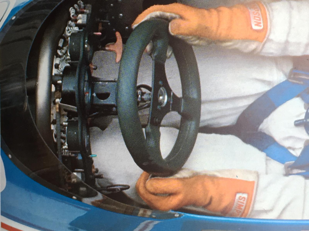
Yes, rocker arms are not recessed in the middle, instead the central metal plate seems in fact a bit higher than the edges, as it seems soldered "ON" them.
My only doubt is the nature of the disk holes: AFAIK round radial holes were only used on carbon discs (seen on a few 1980 pics), and usual thing was typical square "windows", though I'd really be happy to be proved wrong, as it's a much more doable thing!!
Great, great job
PS:
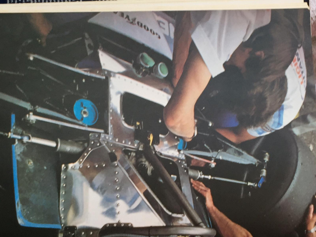
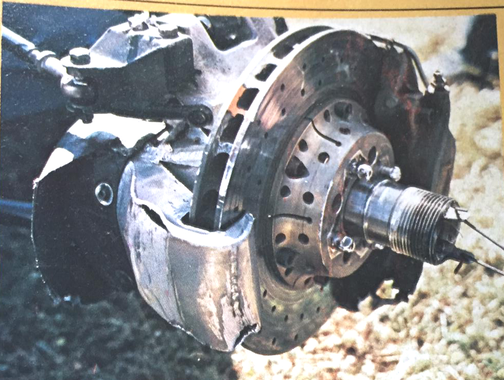
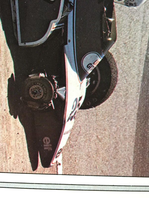
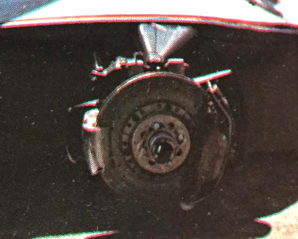
some 1980 brake pics... from Pironi's loose wheel in Jarama.
They could help in some detail as long as it matches the '79 version
Yes, rocker arms are not recessed in the middle, instead the central metal plate seems in fact a bit higher than the edges, as it seems soldered "ON" them.
My only doubt is the nature of the disk holes: AFAIK round radial holes were only used on carbon discs (seen on a few 1980 pics), and usual thing was typical square "windows", though I'd really be happy to be proved wrong, as it's a much more doable thing!!
Great, great job
PS:
some 1980 brake pics... from Pironi's loose wheel in Jarama.
They could help in some detail as long as it matches the '79 version